
This post will be mostly pictures showing how I soldered in the parts. My technique is pretty poor, so don't take this post as guidance on how you *should* do it. Instead, take this post as comfort that you can be bad at soldering and still get things to work just fine.
First, I got my MCP4922 chip from Digikey. Currently, $3.14 each, when bought singly.

I inserted the chip into the PCB. Fits just fine!

I flipped over the PCB to work on the legs of the chip.

I soldered each of the legs:

With all of the legs are soldered, the picture below shows that the joints in the front row are pretty nice, but that the joints in the back row have too much solder. Oh well. I'll try to do better next time.

Upon close inspection, I feel that the legs stick out too far. So, I trim them with my wire snippers. I wish I had better snippers. These don't snip very well. Better ones might let me snip flush against the PCB.

The chip is now fully soldered in place. The next step is to add the connectors around the edge of the board. I could have used male pin headers or female. I only had male headers on hand, so that's what I used. As you can see below, I used a blank proto-board to hold the pins in place so that they poke up straight through my PCB. Then I solder them in place.

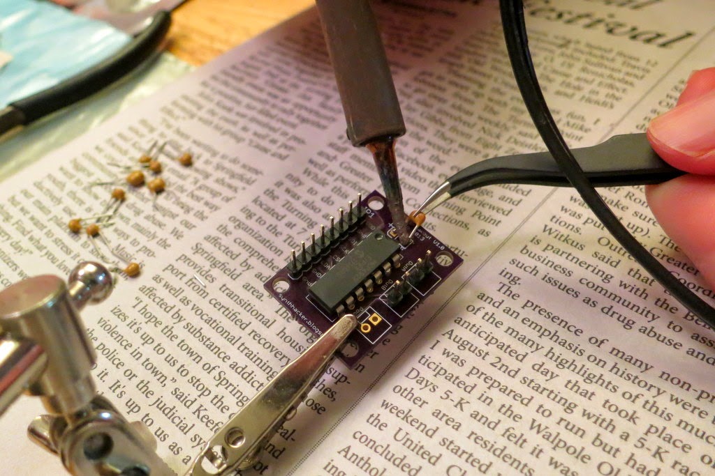
Once all the pin headers are in place, I need to solder in the two caps (10 uF and 0.1 uF) to decouple the power supply. In the design of the PCB, I was bold and made both of them be surface mounted parts. I have barely worked with surface mount components, so I don't really know what I'm doing. In the picture below, you see me starting by tinning the pads. I don't know if this is the right thing to do, but here I go...

After tinning, I try soldering on the surface-mount capacitor. I'm not sure what the best technique is. I had to try it several times until I was able to get both ends of the cap to be decently connected. I am glad that I bought some nice tweezers, though.

So that was the cap on the bottom of the board. The other cap is on the top of the board. Unfortunately, I didn't have another surface mount cap of the right value, so I used a small through-hole cap instead. I snipped the legs really short and tacked it on with solder. This is not recommended, but it got the job done.

With the assembly complete, the next step is to test it. That'll be the next post!
No comments:
Post a Comment